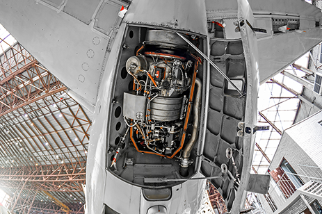
In the simplest terms, a ground is a common return path for electric current and a shared reference point for voltages within a system. In a lab, grounding is pretty easy – plug into a ground terminal, and the room's wiring takes care of the rest. At 30,000 feet inside a vibrating tube filled with electromagnetic interference (EMI), properly grounding hardware is far more complex. If you get it wrong, even the best hardware in the world can produce corrupted data.
This blog discusses why grounding in flight test applications is important, how ground loops form, how to ground multiple pieces of hardware, and ends with a summary of best practices. We're using data acquisition units (DAU) as an example here, but the same logic applies to switches, recorders, etc. For more detailed information, read the Grounding Technical Note that dives deeper into some of the topics discussed here.
Why Grounding is Important
In a flight test, good signal integrity is vital. An aircraft is electrically noisy, and proper grounding creates a path for this noise to dissipate without entering sensitive signal wires. Many of our sensors output tiny voltages. If the ground level at the sensor differs from that at the DAU, even by a small amount, it can drastically distort the actual measurement (a common-mode error).
Grounding is also important for safety. Without a solid chassis ground, a fault in a power supply could energize connected metalwork, including equipment that pilots' might touch.
How do we connect all our equipment so it is properly grounded? In the air, there is no physical wire connected to the earth, so the best common ground will be the airframe itself.
If you are bonding a wire to the airframe, you must first remove any paint or dirt from the surface. You could also apply an anticorrosion treatment to prevent any future oxidation. A conductor can then be bolted firmly to the airframe. However, as we’ve mentioned already, even a large metal object like an aircraft structure has electrical resistance. This unfortunately means that properly grounding electronics in different locations can result in “ground loops”.
Ground Loops
A ground loop occurs when there is more than one conductive path between two points in a grounding system. Because every wire, or aircraft structure, has some electrical resistance, a potential difference will exist between two different grounding points. If you ground two DAUs at different points on the airframe, any stray current flowing through the airframe will create a voltage between those two grounds, causing current to flow through our signal cables.
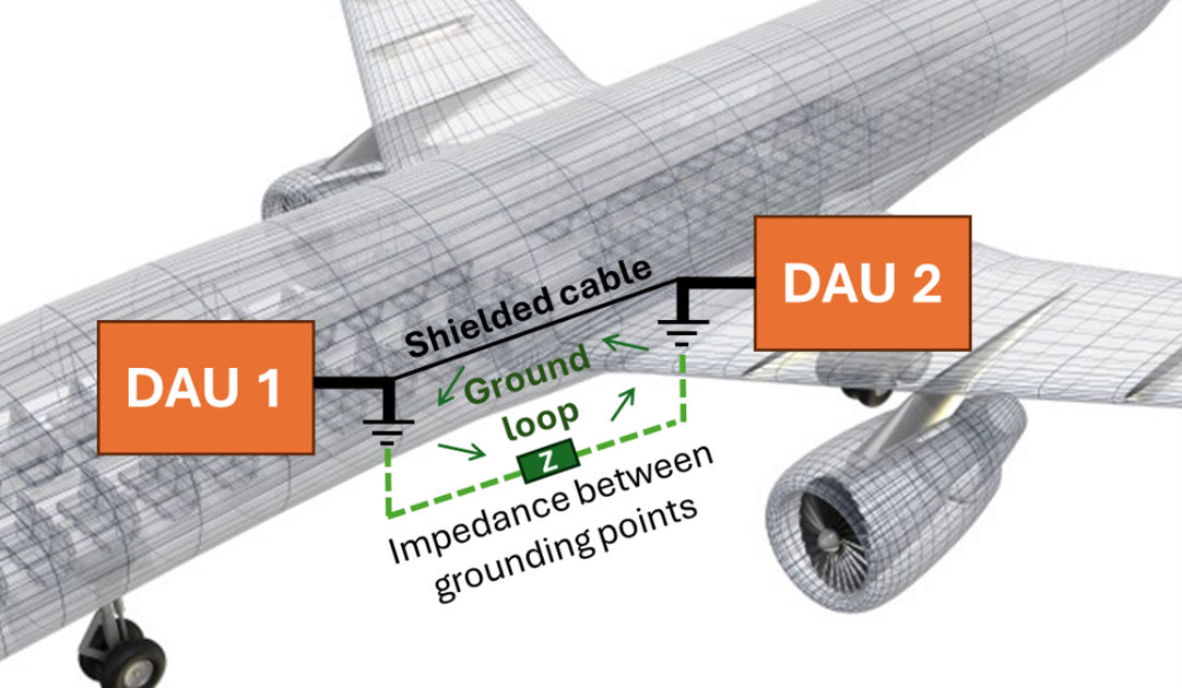
These ground loops cause noisy or distorted data on our signal wires. In extreme cases, a severe voltage swing could even damage sensitive sensors or their wiring. So, how do we stop ground loops? The following are possible tactics:
- Don’t ground anything: While effective against ground loops, we lose the benefits of grounding, i.e., creating a common reference point and safety. This is not recommended.
- Isolate signals using transformers or opto-isolators. Isolators break a signal's physical connection between a sensor and a DAU. These are sometimes used in industrial or professional audio environments but are generally impractical for flight tests due to the large number of sensors and the added cost, weight, and complexity.
- Use balanced connections: Balanced connections use twisted pairs of wires that carry the data on two wires, with the polarity of one signal inverted. By then only measuring the difference between these, any noise picked up on the wires will be rejected. This is effective and commonly employed by some sensors. A disadvantage of this approach is that cables will be more expensive, heavier, bulkier, and less flexible.
- Ground all equipment to a single point on the aircraft: This is also known as a "star-ground" because all wires meet at a single point. A single, high-quality grounding point serves as the sole point of grounding for equipment. You electrically isolate everything from the airframe and run a low-resistance connection from the equipment to this grounding point. This is a well-used and effective approach, but it can be impractical for larger aircraft because it requires running large cables to a central point.
Best practice for grounding FTI systems
The following outlines how to ground your DAUs best, using the KAM-500 as an example. While other DAUs may differ slightly, the principles are the same.
In all cases, using shorter cables is better because they have lower impedance and a lower risk of radio frequency (RF) noise pickup.
CHASSIS connection
For simplicity, we are referring to the physical connection to the DAU metalwork as "CHASSIS”. CHASSIS is also known as the mechanical, shielding, or safety ground. The DAU top blocks, connector frames, and the ground mounting bolt on the PSU are at CHASSIS potential. Most PSU connectors also have a CHASSIS pin.
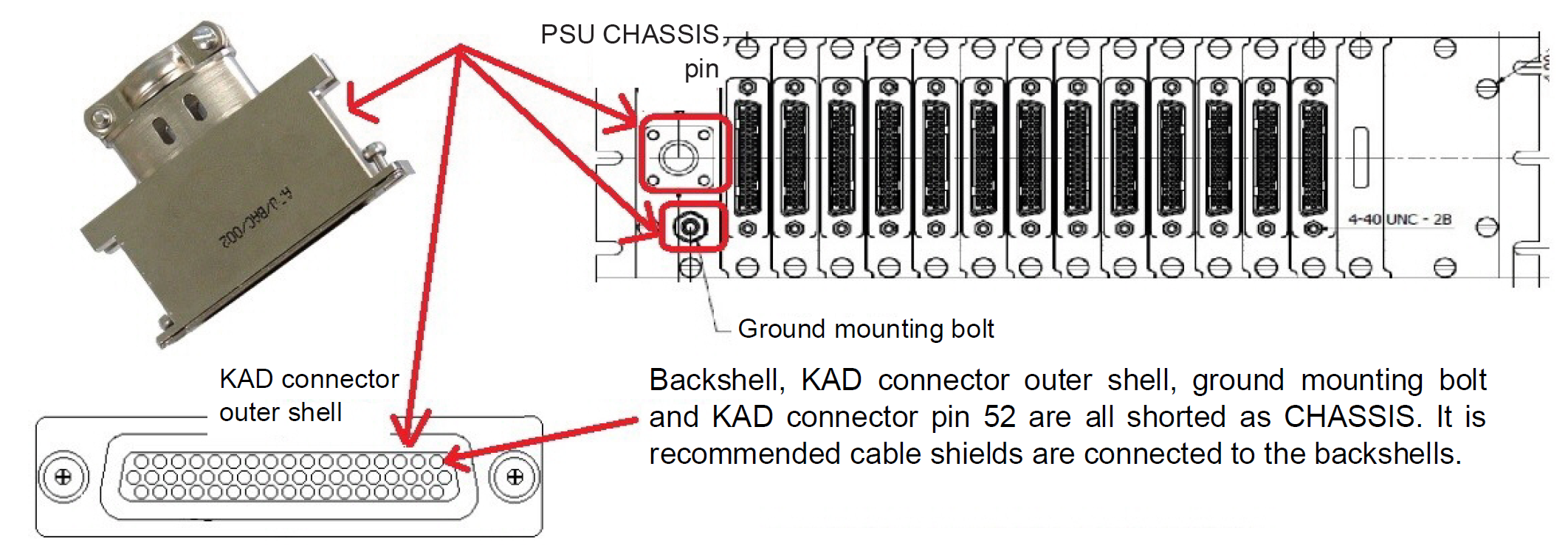
We recommend using the ground-mounting bolt on the PSU with a short braided cable instead of the CHASSIS pin. Braided cable has lower high-frequency impedance than single wires. The chassis mounting bolts can be used for bonding, provided they make good electrical contact (< 50 mΩ) with both the mount and the chassis. To keep GND from floating relative to CHASSIS, while avoiding ground loops, join them together, but at only one point.
POWER(-) connection
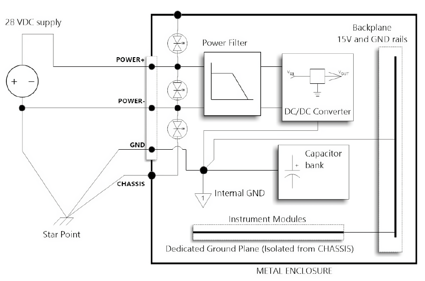
POWER(-) is the return line for the 28V power supply and is not connected to the CHASSIS line nor the GND line within the KAM-500. To improve EMC, we recommend running as a twisted pair with the 28V supply line. POWER(-) must be referenced to the external star point (airframe, or chassis). This can be done at the source of supply, as shown in Figure 3.
Chassis bonding and grounding
We noted earlier that you should connect each isolated ground signal to the main star point on the aircraft or vehicle. Actual aircraft applications may differ from this grounding scheme due to installation issues such as the distance between the power supply, the DAUs, and the airframe, which may act as CHASSIS.
When using more than one chassis, connect each chassis to the star point via an individual cable. Shared cables should not be used. No two chassis should share common cables for the GND, POWER(-), or CHASSIS signals.
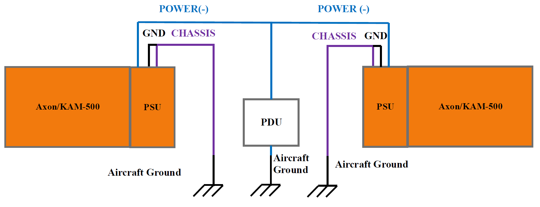
Note: Transient protection devices should be connected to CHASSIS and not GND, as this both shields the DAU's electronics and provides transients with a low-impedance path to the star point.
Cables and shielding
Shielded cable creates a continuous conductive shield envelope (Faraday cage) for the signal lines, incorporating the cable shield, cable clamp, backshell, connector, and top-block. All cables should be shielded, with the shields connected to the DAU CHASSIS via the connector backshells.
Use shield terminations on the backshells or on the backshell cable clamp if you can. Otherwise, you can use a short pigtail and run it from the cable shield to the CHASSIS pin on the DAU connector. This works but is not recommended as it can cause a discontinuity in the shield envelope and will likely have a higher RF impedance than a clamped backshell.
In many analog sensor applications, connecting only one end of the shield may yield better EMC results, for instance, when the predominant noise arises from a potential difference between the signal source and the CHASSIS.
Note that we have found in many instances using high-speed digital signals like Ethernet or MIL-STD-1553 traffic, there is no way to keep the cable quiet without having good shield connections at both ends. Our recommended approach for these cables is to go with the full shielding, then modify on a case-by-case basis if a measurement noise problem is detected.
To avoid ground loops, you may need to insulate the sensor case from the airframe. For instance, as shown in Figure 5, accelerometers may need to be used with insulated bases when mounted on metal airframes to avoid creating a second current path to the DAU module through the airframe. Another technique is to run a parallel earth conductor close to the cable to provide a lower-impedance path between the two points than the cable shield.
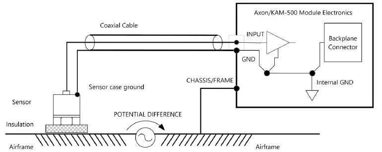
When using sensors powered by an isolated external power supply, you should reference the external power supply ground to DAU GND. When possible, use ±12V or +5V from the DAUs power supply or excitation modules.
Coaxial shielding
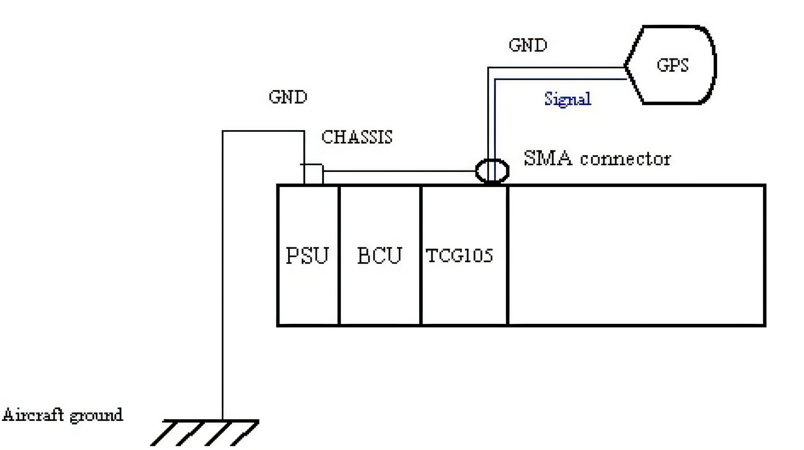
When using coaxial cable from a module to external hardware, e.g., an antenna, GPS, camera, etc., the cable shield behaves as both an RF signal ground and a transient protection ground. Because of this, some modules connect the CHASSIS and GND in the module itself. This introduces the risk of ground loops in the aircraft/test article wiring unless you take care with the wiring design, for example, by using parallel earth conductors.
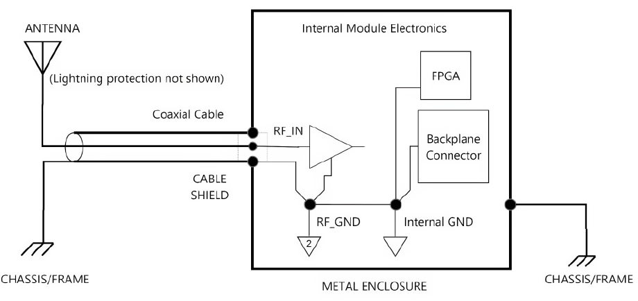
Both CHASSIS and GND should be connected as close to the module as possible, ideally without being linked to anything else. Otherwise, some ground currents may find a path through the chassis and vice versa.
Don’t Forget to Document and Validate Grounding Efforts
The last couple of things to remember is to confirm that you have made good contact with all grounding points and that you have documented what is wired to where.
After connecting the grounds, measure the resistance between each GND point, the CHASSIS point, and the POWER (-) on DAU to the star point. The MIL-STD-464C standard recommends < 10 mΩ from the equipment enclosure to system structure (and <15 mΩ from cable shields to the equipment enclosure.
You should document everything in case of any future noise issues. A month into the test program, knowing which shields are grounded to which module pins, where any grounding straps are located, etc., could vastly speed up troubleshooting when every hour lost is critical.
Final Thoughts and Summary
Grounding isn't just a checkbox task; it is vital for reliable flight testing. Incorrect grounding introduces the risk of corrupted data and of causing delays in the program schedule. To sum up, the following are the basics of good grounding:
- Metal-to-metal: If you are bonding to the airframe, you must remove any paint, oil, or other contaminants.
- Reach for the star: Try to wire distributed units to a single point to help mitigate ground loops.
- Twisted pairs are your friend: For signal wires, use twisted pairs where you can to ensure the DAU can cancel out any EMI picked up on both wires.
- Connect shields to one end: Unless specified by the datasheet or interface control document, only terminate your cable shields at the DAU side. Leave the sensor side floating.
- Validate your efforts: Measure the bond resistance between your hardware and the master GND to ensure it’s <50 mΩ.
- Document everything: Knowing how everything is connected could save vital hours of troubleshooting during test flights.
For more detailed information, read the Grounding Technical Note that dives deeper into some of the topics discussed here.

Subscribe Today!
Subscribe to our blog and receive a monthly email that keeps you up-to-date with the latest news and insights from Curtiss-Wright.

Stephen Willis
Product Marketing Manager
Stephen Willis is the aerospace test and measurement Product Marketing Manager at Curtiss-Wright Defense Solutions. He has a degree in Electrical Engineering, a Masters in Philosophy for research in mathematical models and their market application for risk assessment, and a PG Dip in marketing and management. His current research interests include data acquisition, recording, and control systems and their applications in enabling a cost-effective route to gather large amounts of data. In particular, applications of interest include flight test, crash-protected recording, and structural/usage monitoring programs. He is the author of several academic papers and magazine articles.
