Flight test instrumentation (FTI) engineers rely on these modules to collect data from all the analog sensors installed, converting physical phenomena, such as temperature or vibrations, into electrical signals that engineers can analyze to assess aircraft safety and performance.
A flight test program can face expensive and lengthy delays if the collected data quality and reliability don’t meet acceptable standards. Understanding the technical specifications of these modules is important, as they dictate the quality of the collected data.
What follows is a summary of the most critical specifications you must understand, focusing on core concepts rather than deep technical detail. Deeper technical details are available in TEC/NOT/082.
DC Error: Primary vs. Secondary Gain
The DC error indicates how close the module's reported value is to the true input value from the sensor. This error is affected by the module's amplification circuits or gain stages. It is an important specification for slow-changing measurements such as temperature and strain.
Primary or analog gain refers to the analog amplification factor, also known as true hardware gain, used to utilize the full-scale range of the analog-to-digital converter (ADC). Using a camera as an analogy, it’s like an optical lens – zooming in without losing detail. Secondary, or digital gain, is purely a software artifact that increases the overall performance of a module. Digital gain is like zooming in on a photo – you get a bigger image, but without getting more detail.
The gain stated in a data sheet, the KAD/ADC/109 used as an example here, is a combination of digital gain and analog gain; analog gains are: 1, 10, 100, and 1000. For example, a gain of 400 is composed of an analog gain of 100 and a digital gain of 4. Note that a gain of 1,000 (vs. 1, 10, or 100) decreases performance because it acts like a natural first-order, low-pass filter.
| Gain | Max. error % FSR |
|---|---|
| 1, 10, 100 | 0.08 |
| 2, 20, 200 | 0.14 |
| 4, 40, 400 | 0.25 |
| 8, 80, 800 | 0.44 |
| 1000 | 0.3 |
| 2000 | 0.6 |
| 4000 | 1.2 |
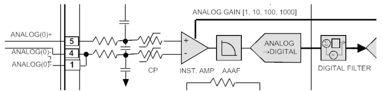
Common-Mode Rejection Ratio (CMRR)
Analog modules typically use differential inputs, meaning they measure the voltage difference between two signal wires. In the electrically noisy environment of an aircraft (caused by motors, avionics, radio waves, etc.), we can exploit the fact that each wire picks up the same unwanted electrical interference.
The common-mode rejection ratio (CMRR) is a measure of the module's ability to cancel out this noise and focus only on the desired signal difference. A higher CMRR is beneficial as it prevents external electrical noise from contaminating low-level signals generated by sensors.
Effective Number of Bits (ENOB)
While an ADC has a theoretical resolution (e.g., 16-bit), real-world noise and imperfections mean not all those bits are truly useful, the effective number of bits (ENOB) is the actual measurement resolution achieved after accounting for all noise and distortion in the system. It is always less than the theoretical bit number.
ENOB is the single best specification for determining the overall dynamic performance and signal quality of an analog module. It tells you the true level of detail you can capture. A high ENOB is critical for capturing subtle or high-resolution data, such as small changes in structural stress or fine aerodynamic pressures.
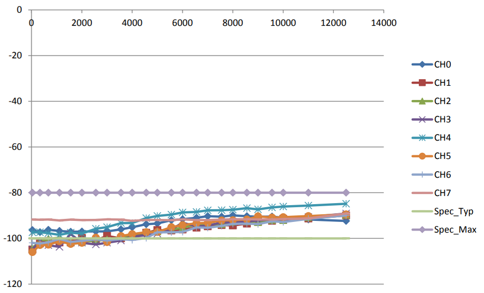
Crosstalk
Since modern FTI modules have very high channel density, the signal from one acquisition channel may leak into an adjacent channel. This unwanted noise is called crosstalk. If a high-amplitude signal contaminates a low-amplitude channel through crosstalk, the data from the low-amplitude sensor will be corrupted and potentially unusable; therefore, it is essential to minimize this occurrence.
Common Mode Range
The common mode range is the operational voltage range. If a sensor circuit's ground voltage drifts or is slightly different from the acquisition system's ground, as long as it is within the common mode range of the module’s input, the module won't be damaged and the measurement will remain valid.
Digital Filter Attenuation
Digital Filter Attenuation describes how much the filter reduces the amplitude of unwanted high-frequency signals at a specific frequency. The primary role of the filter is to prevent aliasing. Without sufficient filtering, high-frequency noise that is irrelevant to your measurement can be "folded back" by the sampling process into your desired low-frequency bandwidth, corrupting your results. Proper attenuation ensures a clean signal and accurate analysis.
| Parameter | Min. | Typ. | Max. | Units | Condition/Details |
|---|---|---|---|---|---|
| Analog filter |
|
|
|
| Analog filter is Butterworth. |
| Poles | - | - | 4 | - | |
| filter cutoff -3dB | 11.4 | 12 | 12.6 | kHz | |
| Digital Filter |
|
|
|
| Digital filter is Butterworth. |
| Poles | - | - | 8 | - | |
| filter cutoff -3dB | 0.25 | - | 16 | fs | The maximum value is limited to 6kHz (fs: sampling frequency). |
| 0.1dB bandwidth | - | 0.8 | - | fc | |
| aliasing to 0.1dB band | - | - | -72 | dB | |
| aliasing to fc | - | - | -74 | dB | |
| Filter delay | - | 0.33 | - | ms | Where fin = fc = 6kHz (fin: input signal frequency). |
Summary
Understanding these specifications enables you to select the appropriate module for the task, ensuring that the valuable and expensive flight test data you collect is trustworthy and suitable for certifying an aircraft. A summary of these specifications is shown in the table below.
| Specification | Simple Explanation | Why It Matters to FTI |
|---|---|---|
| Common-Mode Rejection Ratio (CMRR) | The module’s ability to ignore unwanted noise that appears equally on both signal wires. | Ensures you are only measuring the intended signal, not the electrical interference. |
| Common-Mode Range | The maximum voltage the module can tolerate without damage or incorrect readings. | Ensures the module won't be damaged by large potential and defines the operational voltage range. |
| Crosstalk | The amount of signal "leakage" from one data channel to another. | We need this number to be extremely low (high attenuation in dB) to ensure data isn’t corrupted by mixing unrelated signals. |
| DC Error (Accuracy) | How accurately DC voltage is measured. | Low DC error improves the accuracy of sensors, especially low sample rate ones such as temperature or strain. |
| Effective Number of Bits (ENOB) | A measure of a module's true, usable resolution after accounting for system noise. | The higher the ENOB, the finer the detail you can measure - vital for analyzing subtle changes. |
For more details, read the technical note TEC/NOT/082.

Subscribe Today!
Subscribe to our blog and receive a monthly email that keeps you up-to-date with the latest news and insights from Curtiss-Wright.

Stephen Willis
Product Marketing Manager
Stephen Willis is the aerospace test and measurement Product Marketing Manager at Curtiss-Wright Defense Solutions. He has a degree in Electrical Engineering, a Masters in Philosophy for research in mathematical models and their market application for risk assessment, and a PG Dip in marketing and management. His current research interests include data acquisition, recording, and control systems and their applications in enabling a cost-effective route to gather large amounts of data. In particular, applications of interest include flight test, crash-protected recording, and structural/usage monitoring programs. He is the author of several academic papers and magazine articles.