Designing the critical flight test instrumentation (FTI) systems that validate aircraft performance requires more than selecting the right sensors and data-processing hardware; it demands a rigorous approach to power management and thermal regulation.
Engineers need to ensure that data acquisition units (DAU), switches, recorders, etc., don’t draw more power than the aircraft can reliably provide. Additionally, every DAU's configuration needs analysis to ensure power converters are not overloaded and that there is sufficient heat dissipation to avoid out-of-spec performance or failure due to heat build-up.
This blog explains how to calculate power consumption and dissipation for DAUs, with worked examples. We compare the results for a theoretical DAU with those for a real DAU and offer some advice for field deployment. More detailed information can be found in TEC/NOT/049 - Power estimation and TEC/NOT/016 -Power dissipation, an example.
Estimating a DAU’s Power
For illustrative purposes, we will use the KAM-500 DAU for our calculations. Every DAU is different, so the exact details for estimating power draw may vary slightly across DAU families, but the principles are universal.
Estimating the power draw of a DAU to a reasonable accuracy requires knowing the following:
- The power draw of the chassis
- The current draw from each power line of each module
- Any excitation power provided to sensors
- The DAU’s power supply DC/DC converter efficiency
You can get most of the required information from the hardware's datasheets. Note that the current drawn by a module varies depending on factors such as the module's sampling frequency, the output/input rate for bus modules, or the excitation applied at the module's output.
Each PSU has a limited current amount available per power line. If there are multiple powerlines (the KAM-500 has +5, ±7, and ±12 V), then the sum of current used on each line must be checked against the total current available from the PSU of the chassis. It is also important to ensure the current drawn between the positive and negative lines of the different voltage lines is balanced correctly, or the imbalance may compromise DC/DC stability. For example, in the KAM-500, when an imbalance reaches 7:1, the voltage on the opposite line may vary within ±10%.
DC/DC Converter Efficiency Charts
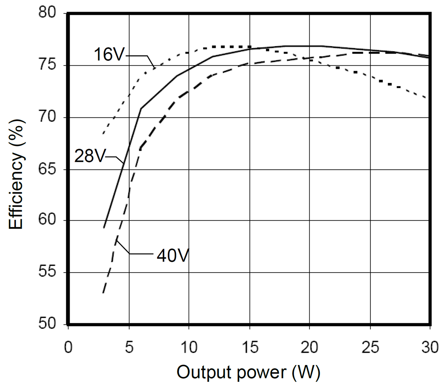
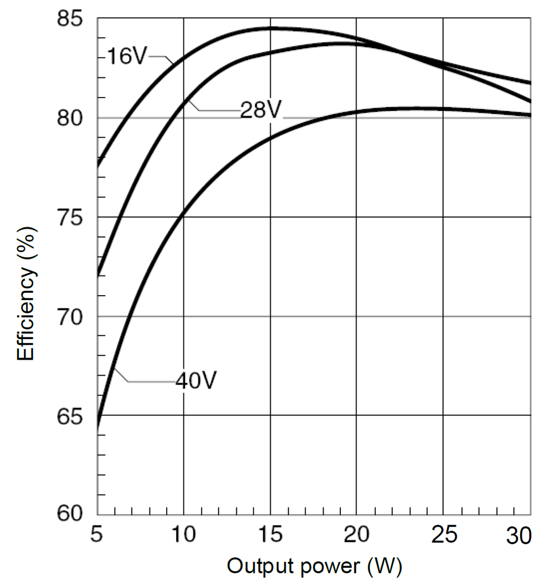
The DC/DC converters used in units like the KAM-500 do not operate at a fixed percentage – their efficiency varies with the output power and the voltage of the external supply. Figure 1 and Figure 2 show the DC/DC converter efficiency used on the KAM/PSU/012.
Power Draw: A Worked Example
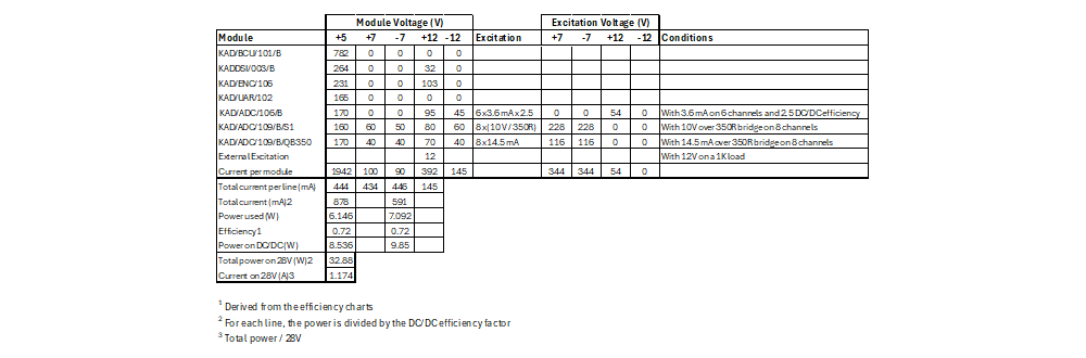
The following is an example of how you would estimate the power drawn by a DAU. In this case, it is a 13-slot KAM-500 (KAM/CHS/13U) with a KAM/PSU/012 power supply, a PCM controller, and a mix of data acquisition and encoding modules as listed in Table 1. The estimated power draw is about 33 W, which is well below the 56 W recommended for the KAM/PSU/012.
Power dissipation - a worked example
Once we know how much power a DAU can draw, the next question is how a DAU gets rid of that energy. Basic physics tells us that there are three ways to dissipate heat: conduction, convection, and radiation. As the effectiveness of conduction depends heavily on the mounting method and surface characteristics, we will limit our estimation to convection and radiation. Please note that conduction is highly effective at removing heat and should be exploited where possible.
For the worked example, the system detailed in Table 2 was powered using a 28 V supply and mounted on an insulator (to eliminate conduction cooling) in a black room at an ambient temperature of 26.1 °C. The power consumption of the system is calculated as shown in the following table:
| Item | Power [W] | Number | Total Power [W] |
|---|---|---|---|
| KAM/SYS/13U | 5.1 | 1 | 5.1 |
| KAM/ADC/005 | 2.0 | 7 | 14 |
| KAM/MSB/001 | 1.0 | 2 | 2 |
| KAD/UAR/001 | 0.6 | 1 | 0.6 |
| KAD/ADC/001 | 1.6 | 1 | 1.6 |
| KAD/ADC/0091 | 2.9 | 2 | 5.8 |
| Bridges (External) | 0.29 | 16 | 4.6 |
| Bridges (internal) | 0.11 | 16 | 1.8 |
| Total (excluding DC/DC losses) |
|
| 35.5 |
| Total (including DC/DC losses) |
|
| 42.6 |
| Total power consumed internally |
|
| 38.0 |
We constructed an identical system and placed it in the same environment; we measured the total power draw at 40.9 W, about 4% lower than the calculated 42.6 W. This margin of error is due to variations from module to module, external connections, power efficiency, and so on.
Calculating Power Dissipation
The ambient (air) temperature was 26.1 °C, and the case temperature of the KAM/SYS/13U settled at 54.1 °C.
The power radiated from a DAU can be approximated using the equation:
Prad = ѲRad (TKAM4 - Tsurface4)
where:
- Prad: Radiated power
- TKAM: Case temperature of the DAU (54.1°C or 327.25 °K)
- Tsurface: Equivalent black surface temperature (26.1 °C or 299.25 °K) of the surrounding enclosure (assumed to be ambient)
- ѲRad: Radiation coefficient (5.78 x 10⁻⁹ for this form factor
Filling in the values we get: 5.78 x 10⁻⁹ (327.254 – 299.254) = 19.9 W
For the heat transfer due to natural convection in still air, at sea level, from a DAU can be approximated using the equation:
Pconv = Ѳconv(TKAM – TAMB)1.25
- Pconv: Natural convection heat transfer
- TKAM: Case temperature (54.1 °C)
- TAMB: Ambient air temperature surrounding the housing (26.1 °C)
- Ѳconv: Convection coefficient (0.21 for this form factor)
This gives us: Pconv = 0.21 (54.1 – 26.1)1.25 = 13.5 W.
Theory vs. Practice and Important Lessons
According to the above equations, the total power dissipated is = 33.4 W (19.9 W + 13.5 W). We measured the total power dissipated in the real system at 36.3 W, about 9% higher than the calculated value. This shows that, similar to the power draw calculations, you can get a reasonable estimate for the power dissipation, as you can for power drawn calculations.
But of course, data acquisition doesn't happen in a black room at 26.1 °C; it happens in cramped bays, unpressurized cabins, and varying altitudes. In a small, low-airflow area, convection effectively ceases. This is also true at higher altitudes, where lower pressure means there is less air, though the ambient temperature will likely also be lower.
In most applications, power is also dissipated via conduction, as engineers typically mount DAUs on a metal support frame. If the calculations for power dissipation via radiation and convection are insufficient, special attention may be needed to how DAUs are cooled. Possibilities include using custom mounts to maximize thermal contact, using heat sinks to increase DAU surface area, or adding active cooling solutions. Another option is to use multiple smaller DAUs that each draw less power and have relatively larger surface areas than one large DAU.
Whatever approach one takes, the first step is to estimate the likely power usage and dissipation. Knowing this at the system planning stage will inform engineers of any potential issues before finalizing designs and installing equipment.
Ensuring DAUs don't overheat is vital to acquiring good-quality data. For more detailed information, you can read the following technical notes: TEC/NOT/049 - Power estimation and TEC/NOT/016 -Power dissipation, an example.

Subscribe Today!
Subscribe to our blog and receive a monthly email that keeps you up-to-date with the latest news and insights from Curtiss-Wright.

Stephen Willis
Product Marketing Manager
Stephen Willis is the aerospace test and measurement Product Marketing Manager at Curtiss-Wright Defense Solutions. He has a degree in Electrical Engineering, a Masters in Philosophy for research in mathematical models and their market application for risk assessment, and a PG Dip in marketing and management. His current research interests include data acquisition, recording, and control systems and their applications in enabling a cost-effective route to gather large amounts of data. In particular, applications of interest include flight test, crash-protected recording, and structural/usage monitoring programs. He is the author of several academic papers and magazine articles.