
In flight testing, understanding the stress and deformation experienced by the aircraft's fuselage, wings, and other components is vital to comprehending the aircraft's structural limits during a maneuver. We cannot measure internal "stress" directly, but we can measure strain on the surface of the aircraft and use the material properties to calculate the stress. The strain gauge is the most often used sensor to measure strain, and this blog presents an overview of the sensor and how to best acquire accurate data from it. For more detailed information, including equations for various bridge configurations, please refer to this technical note.
The Strain Gauge
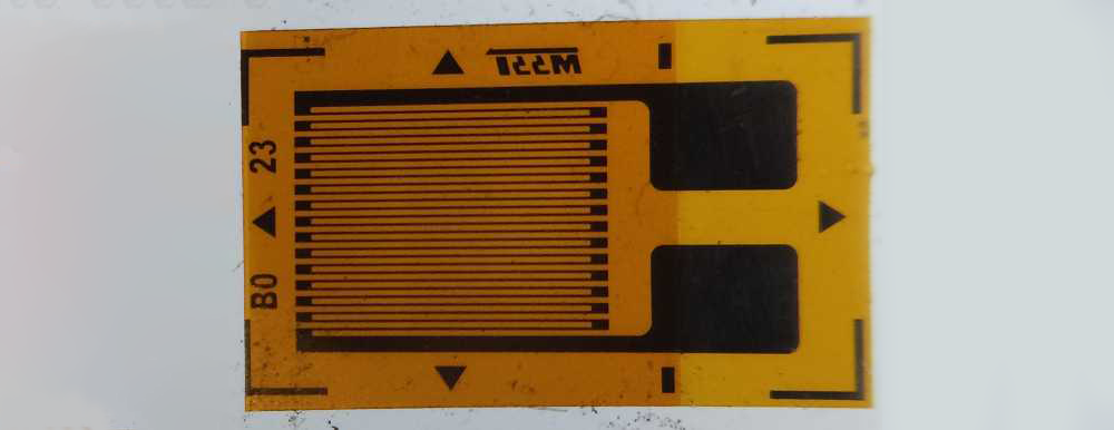
A strain gauge is a very thin wire or foil grid bonded to the aircraft's surface. As the surface stretches, the gauge stretches, which increases its electrical resistance (since the wire becomes longer and thinner). A strain gauge’s Gauge Factor tells you about the relationship between a change in resistance and the change in strain. It is important to correctly enter this value in your software, or you will get incorrect measurements.
Compensating for Bonding and Temperature Errors
Bonding gauges to a structure must be done with great care. If the gauge is not parallel to the strain under measurement, or is not flat, it will cause a gain error. But perhaps the biggest "enemy" of a strain measurement is temperature. As an aircraft climbs, the ambient air gets colder, causing the airframe and the gauge to contract. This looks like "strain" to our sensors, even if there is no load on the wing. Without proper temperature compensation, your data may suggest the wing is in danger of breaking when it's actually just cooling.
There are a few ways to compensate for temperature changes:
- Use gauges manufactured to match the expansion rate of specific materials (like aluminum or steel).
- Place a second dummy gauge nearby but not under load. Since it experiences the same temperature, we can subtract its "fake" strain from our primary measurement.
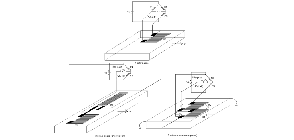
- Use bridge circuits that have the advantage that the absolute resistance values of bridge arms are less important than the ratio, so that gauges can have compensation arms
Wheatstone Bridges
While a bridge circuit can help compensate for temperature changes, perhaps more importantly, it can also convert the tiny resistance change from a single strain gauge into a measurable voltage. The most common bridge is the Wheatstone Bridge.

Wheatstone bridges are so effective because if the ratio on one side equals that on the other (R2/R1 = R4/R3), then the output voltage (Vo) is 0 V. The fact that the ratios, not the gauge resistance, directly determine the output allows more sensitive measurements and enables compensation gauges to correct bonding and temperature errors. Figure 3 shows an example of using compensation strain gauges in a bridge.
Selecting the Right Bridge
We categorize bridges based on the number of "active" arms that contain strain gauges, as shown in Table 1. A full bridge provides the "cleanest" signal with the least noise, but it requires more wiring and gauges. Since weight and space are at a premium on a flight test aircraft, you will often have to choose between the high accuracy of a full bridge and the simplicity of a quarter bridge. Nothing is stopping you from mixing different bridge types for various locations on an aircraft. Although some data acquisition modules are optimized for high-channel density acquisition of a single bridge type, many can accommodate multiple types.
| Bridge Type | Active Gauges | Description | Typical Use | Example Modules |
| Quarter Bridge | 1 | One gauge measures strain; others are fixed resistors. | Simple tension/compression. | KAD/ADC/113, AXN//ADC/406 |
| Half Bridge | 2 | Two gauges; usually one in tension and one in compression. | Bending or temperature compensation. | SCD-116D-3, AXN/ADC/404, |
| Full Bridge | 4 | All four arms are active gauges. | Maximum sensitivity; torque or high-load bending. | MSCD-108D, KAD/ADC/135 |
Additionally, full bridges are inherently linear, meaning that if the strain is doubled, the voltage is also doubled. Quarter bridges have a slight non-linearity, which we often have to correct mathematically in the data acquisition system. Knowing which bridge types are non-linear allows you to apply the correct "transfer function" in your post-flight analysis to ensure the pilots are seeing the true structural load.
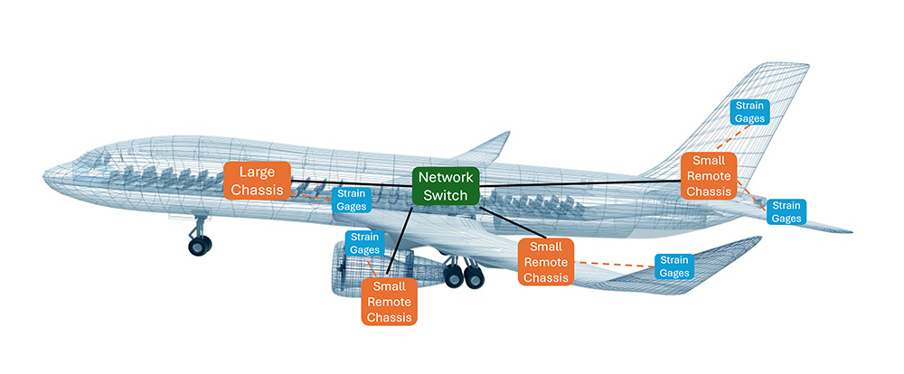
A final consideration that applies to all bridges is accounting for the excitation and sense wires connecting the strain gauge to the data acquisition unit (DAU). If you don't account for wire resistance, your measurements will be consistently lower than reality, and longer cable runs will also result in weaker signals. A good strategy is to locate DAUs close to sensors, which can involve selecting a mixture of DAU chassis sizes to best balance channel density with installation flexibility.
Conclusions
This blog introduces the basics of strain gauge measurement, sources of error, and the use of Wheatstone bridges. More detailed information, including equations for different bridge configurations and their associated sensitivities, can be found here. A variety of chassis sizes and modules are available here.

Subscribe Today!
Subscribe to our blog and receive a monthly email that keeps you up-to-date with the latest news and insights from Curtiss-Wright.

Stephen Willis
Product Marketing Manager
Stephen Willis is the aerospace test and measurement Product Marketing Manager at Curtiss-Wright Defense Solutions. He has a degree in Electrical Engineering, a Masters in Philosophy for research in mathematical models and their market application for risk assessment, and a PG Dip in marketing and management. His current research interests include data acquisition, recording, and control systems and their applications in enabling a cost-effective route to gather large amounts of data. In particular, applications of interest include flight test, crash-protected recording, and structural/usage monitoring programs. He is the author of several academic papers and magazine articles.