Today, flight test instrumentation (FTI) engineers install a variety of sensors throughout an aircraft to measure phenomena such as temperature, vibrations, and stress.
Many of these sensors output analog signals to data acquisition units, which convert them into digital data for storage, transmission, and data analysis. FTI engineers must ensure that the conversion from analog to digital produces accurate and reliable data in a noisy and complex aerospace environment. The process of filtering—removing unwanted signal components, like electrical noise—is fundamental to this.
The following blog explains the core concepts behind converting a physical signal into useful digital data and how we clean it up using both analog and digital techniques. You can download the technical note TEC/NOT/019 for more extensive information including descriptions of different filter algorithms and their characteristics.
Sampling
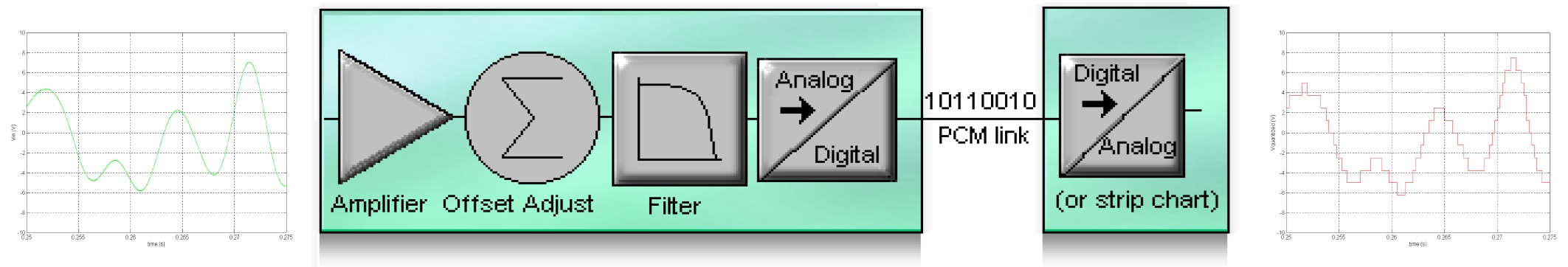
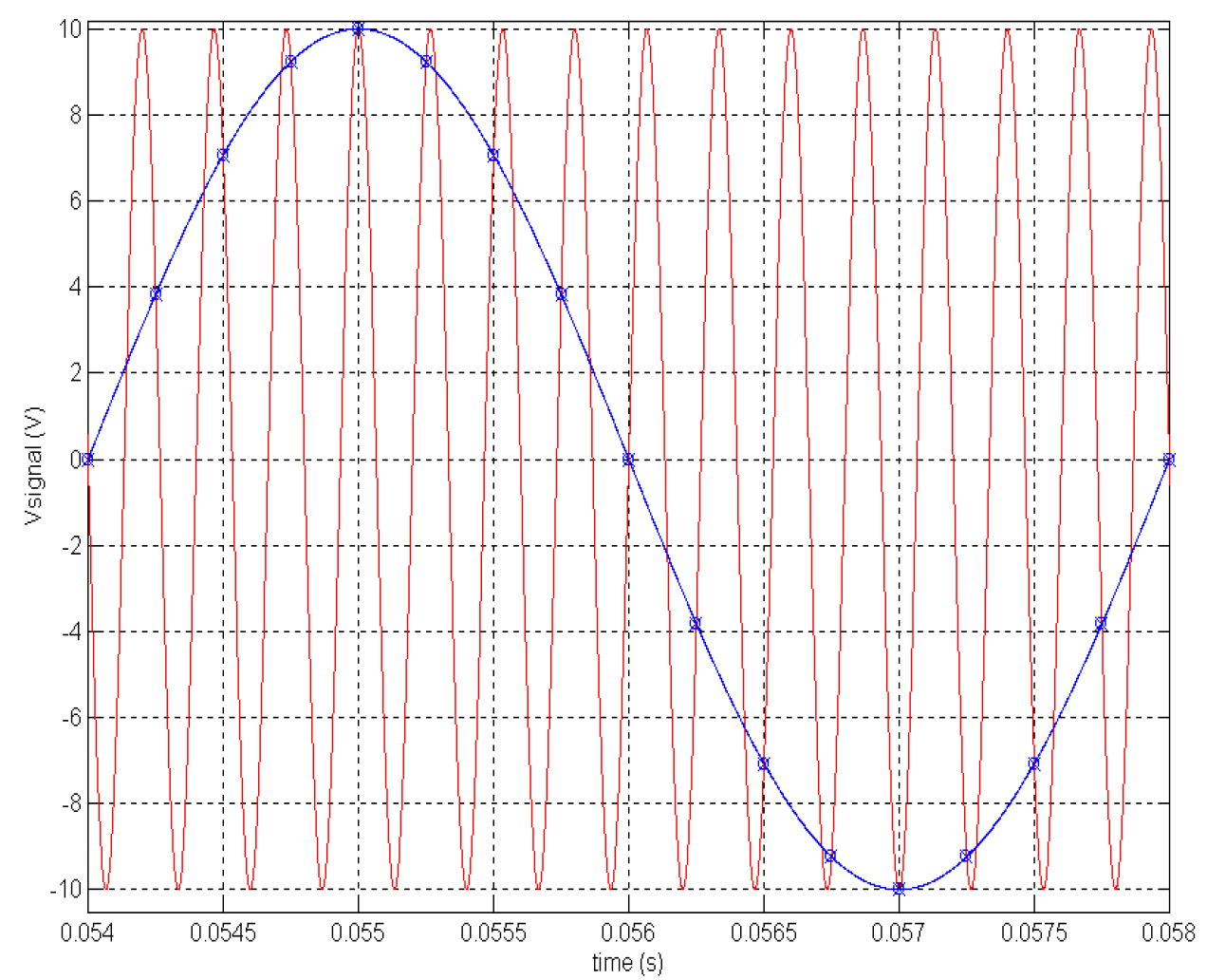
To analyze a continuous real-world signal (like pressure or vibration) using a computer, we must first convert it into a discrete digital signal. This is a two-step process: sampling and quantization. Sampling takes snapshots of the signal's amplitude at regular intervals. The maximum frequency a system can accurately reproduce is known as the Nyquist frequency, which is exactly half of the sampling rate. If we sample a signal too slowly, aliasing occurs, where a high-frequency component is incorrectly interpreted as a lower frequency. Quantization is the process of assigning a discrete numerical value to each amplitude snapshot, converting the analog voltage into a binary number that a computer can store and process.
Analog Filters
Before an analog signal reaches the digital converter, we use analog filters, often called anti-aliasing filters (AAFs), to remove any high-frequency noise above the Nyquist frequency. Otherwise, if a high-frequency noise component is sampled, it will "fold down" into the useful part of the frequency range, corrupting the data through aliasing. Filters ensure that only the relevant signal frequencies are sampled.
Quantization Noise
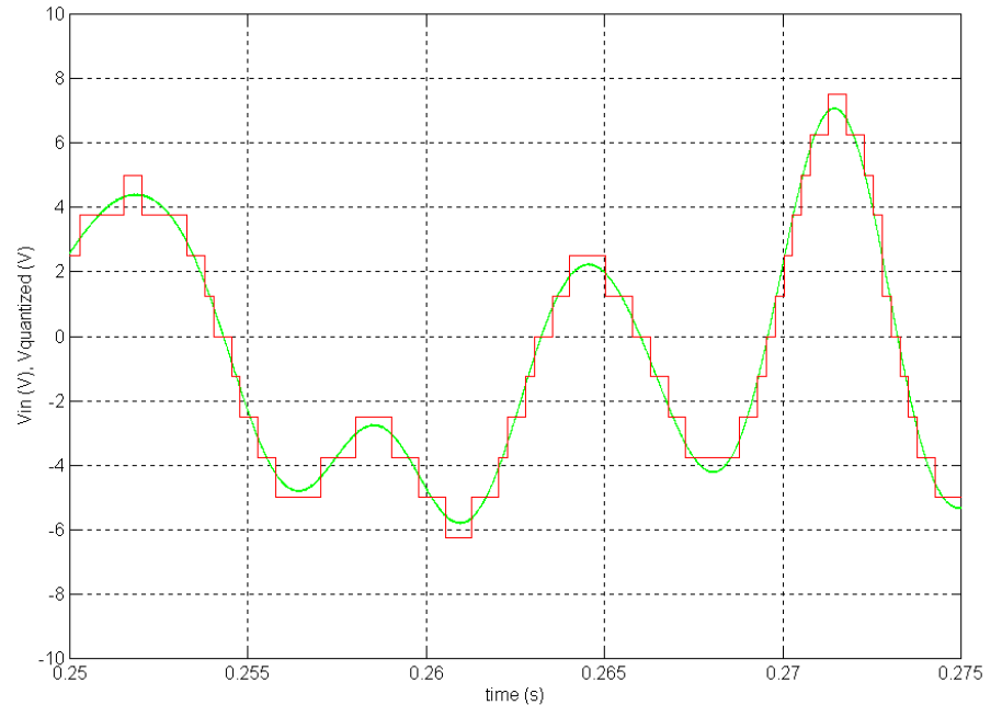
When converting an analog signal to a digital number, its continuous amplitude must be approximated or "rounded" to the nearest available digital step. This unavoidable rounding error is known as quantization noise.
In data acquisition, the step size between digital values is determined by the resolution of the analog-to-digital converter (ADC), usually expressed in bits. The more bits the ADC has (e.g., 24-bit vs. 12-bit), the smaller the digital steps, and the lower the quantization noise. This noise is typically modeled as a low-level, random background noise.
Digital Filtering
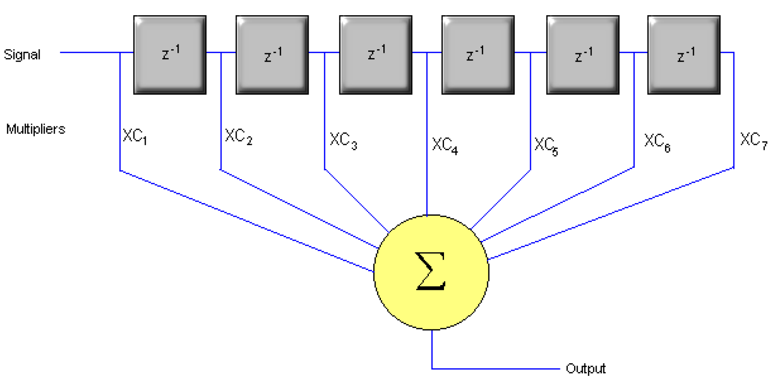
Once the signal is in the digital domain, digital filters provide powerful, flexible, and extremely precise methods for cleaning and shaping the data. Unlike analog filters, digital filters are implemented using mathematical algorithms in a processor (like a DSP chip).
The key advantages of digital filters are:
- Precision and stability: Stored coefficients (numbers) determine their characteristics (like the cutoff frequency), not physical components that can drift with temperature or age.
- Flexibility: The filter's properties can be changed instantly simply by loading a new set of coefficients.
The two main types are finite impulse response (FIR) and infinite impulse response (IIR) filters, which use different calculation methods to achieve the desired filtering effect. Digital filters provide the final, highly accurate cleanup of the signal for analysis.
Summary
Flight test engineers rely on good data to properly evaluate aircraft performance and gather certification evidence. Converting from the analog world into the digital is just one of many steps along this path. This blog covered the foundational process of converting a continuous physical signal into a discrete digital signal that can be further processed, Table 1 summarises these concepts.
| Concept | Explanation | FTI Importance |
|---|---|---|
| Sampling | Taking snapshots of the analog signal's amplitude at regular time intervals. | Determines the maximum measurable frequency. |
| Nyquist frequency | Exactly half the sampling rate (f/2), the highest frequency you can accurately capture. | You must sample at least twice the frequency of interest. |
| Aliasing | Occurs when sampling a frequency above the Nyquist frequency. The noise signal incorrectly "folds down" and appears as a false, lower-frequency signal in your data. | Corrupts data. Aliased data is invalid and cannot be fixed later. |
More in-depth details can be found in the TEC/NOT/019 technical document.

Subscribe Today!
Subscribe to our blog and receive a monthly email that keeps you up-to-date with the latest news and insights from Curtiss-Wright.
Stephen Willis
Product Marketing Manager
Stephen Willis is the aerospace test and measurement Product Marketing Manager at Curtiss-Wright Defense Solutions. He has a degree in Electrical Engineering, a Masters in Philosophy for research in mathematical models and their market application for risk assessment, and a PG Dip in marketing and management. His current research interests include data acquisition, recording, and control systems and their applications in enabling a cost-effective route to gather large amounts of data. In particular, applications of interest include flight test, crash-protected recording, and structural/usage monitoring programs. He is the author of several academic papers and magazine articles.